| Package Dimensions | 5.63 x 4.13 x 0.83 inches |
| Item Weight | 0.634 ounces |
| ASIN | B0CHDRF497 |
| Customer Reviews | 4.3 out of 5 stars 9Reviews |
| Date First Available | September 6, 2023 |
| Manufacturer | EC Buying |
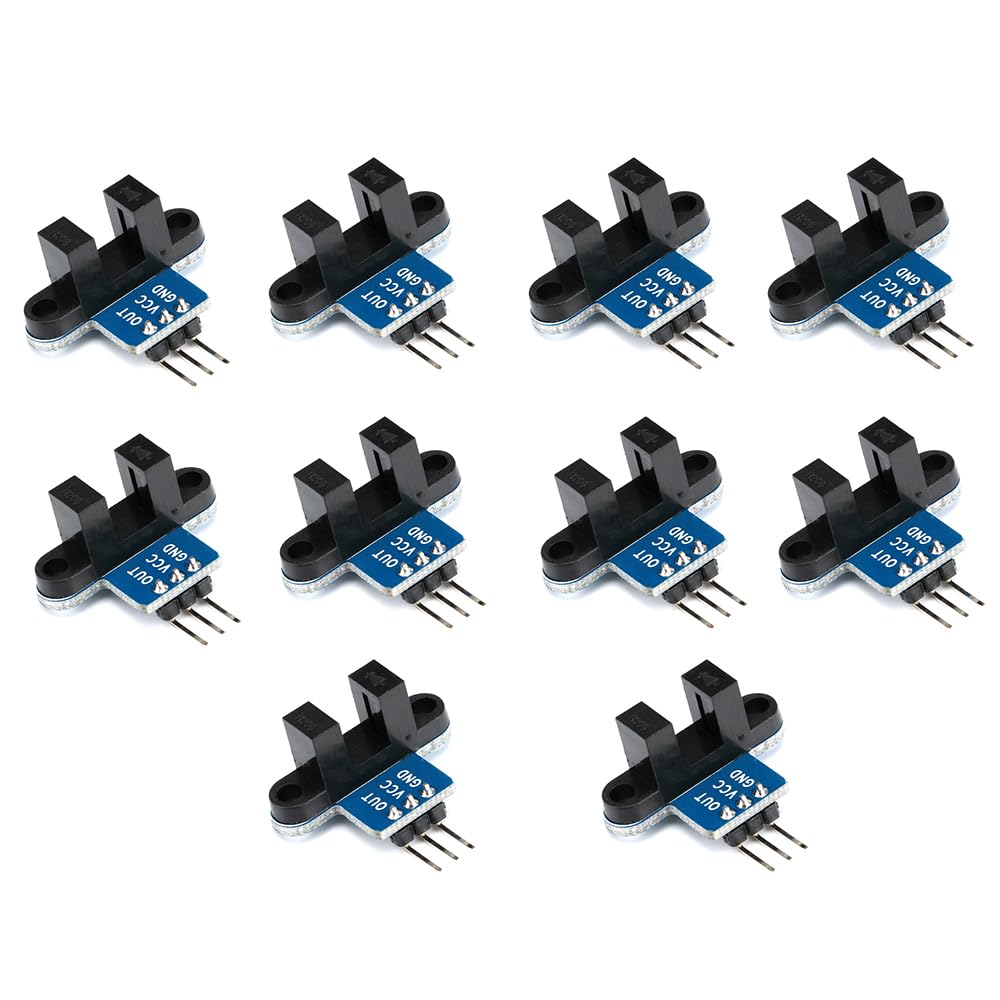
Instructions for use:
After connecting VCC and GND, the module signal indicator light will light up. When there is no obstruction in the module slot, the receiver tube will conduct and the module OUT will output a high level; When obstructed, OUT outputs a low level and the signal indicator light goes out. The module OUT can be connected to a relay to form a limit switch and other functions, and can also be connected to an active buzzer module to form an alarm. The OUT output interface can be directly connected to the IO port of the microcontroller, usually connected to an external interrupt to detect whether the sensor is blocked. If a motor encoder is used, the speed of the motor can be detected.
Precautions:
Correct wiring! Do not reverse the positive and negative connections to burn out the electronic components of the board. Players should set the I/O port of the MCU to input mode/receive mode, otherwise it cannot be used. Other MCUs, or more advanced control boards such as ARM, must be set to input/output mode if the I/O port needs to be set to input/receive mode, otherwise it cannot be used. The 51 series microcontroller can be used directly without the need to set input and output modes.